
- Nrf52 sdk on segger embedded studio how to#
- Nrf52 sdk on segger embedded studio driver#
- Nrf52 sdk on segger embedded studio software#
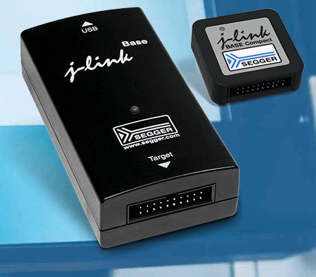
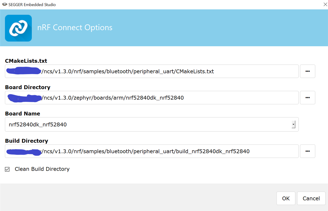
Set a breakpoint on the LEDS_INVERT() line.Connect your board to the USB port and press F5 to begin debugging.Ensure you check the “Reset device after programming” checkbox: Each setup has its own advantages and drawbacks. Other alternatives are Keil uVision, IAR, and GCC with Makefile. You can use Segger Embedded Studio, which is an Eclipse-based integrated development environment. Select Segger J-Link as the debug method. There are several options when writing firmware for Nordic nRF52.If you are using nRF52-DK, select the PCA10036 board:
Nrf52 sdk on segger embedded studio driver#
Understanding nRF52 PPI module and nrfxppi driver Learn about the Programmable Peripheral Interconnect (PPI) module in Nordic nRF52 family and the nrfxppi driver to control it. In this example we will build the simplest LEDBlink sample, however you can select a different one and follow one of our nRF51 tutorials to see Bluetooth LE functionality in action. Setup and debug a Nordic nRF52 application using Visual Studio Code and Cortex-Debug extension with ease.
Nrf52 sdk on segger embedded studio how to#
pressing button 1 will toggle LED 1.This tutorial shows how to develop and debug a basic firmware for the nRF52 devices with Visual Studio and VisualGDB. Pressing a button will toggle the respective LED i.e. If the pin state is still LOW, then we toggle the state of the respective LED’s pin.īuild the project and program the nRF52 DK.

If a pin goes LOW, we wait for 150ms and then check the pin state again. It constantly checks for the state of each pin. This block of code is placed in an infinite while in main. You can try different values between 50 ms to 500ms and notice the difference in behaviour of the LEDs. I have used a delay of 150ms but this can be changed according to what you feel is suitable for you.
Nrf52 sdk on segger embedded studio software#
There are multiple hardware and software methods on fixing the debounce problem but the easiest is to use a delay. The debounce delay is to avoid these transitions. Once they are properly conducting, the signal is stable. But when we look at the electrical signal, there are often multiple transitions when the two pieces of metal in the button make contact. When we press a button, we assume that it is simple transition from HIGH to LOW state. The DEBOUNCE_MS macro is quite essential for properly detecting a button press. It is a good practice to define all constants like the pin numbers for the LEDs and buttons should be defined as macros. #define LED_1 17 #define LED_2 18 #define LED_3 19 #define LED_4 20 #define BUTTON_1 13 #define BUTTON_2 14 #define BUTTON_3 15 #define BUTTON_4 16 #define DEBOUNCE_MS 150 “nrf_gpio.h” includes the functions for controlling the GPIO and “nrf_delay.h” has the nrf_delay_ms function which is a very easy method to introduce delays.

The above two headers need to be included. Code overview: #include "nrf_gpio.h" #include "nrf_delay.h"


 0 kommentar(er)
